
Ultrasonography
Introduction
Ophthalmic ultrasonography uses the reflection or echoes of high frequency sound waves to define the outlines of ocular and orbital structures.
Ultrasonography also aids the physician in detecting the presence of abnormalities such as tumours and determining their size, composition and position with in the eye.
Ultra sound procedures are divided into two types:
- A-Scan ultrasonography
- B-Scan ultrasonography
A-Scan : Time Amplitude Display
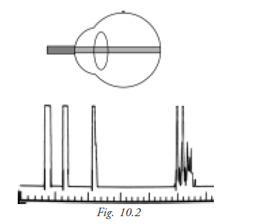
It is a one dimensional display, where echoes are depicted as vertical deflections from a baseline. The strength of an echo is indicated by the amplitude (height) of the spike.
Introduction
A-scan biometry is also called axial length measurement, or simply “A-scan" or "A's". This measurement is combined with keratometry ("A's and K's") in a formula to determine the power of the intraocular lens that replaces the natural lens removed from the eye during cataract surgery.
Reflectivity
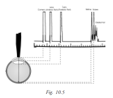
The A-scan probe projects a thin sound beam that travels through liquid or tissue. When the A-scan beam is projected into the phakic (natural lens) eye it travels through the aqueous humor and encounters a dissimilar substance in the anterior lens surface causing a spike.
Strong reflections also occur as the sound beam encounters the posterior lens surface and the retina. Spikes representing these reflections appear at their corresponding positions along the baseline. The first spike represents the probe tip as it comes into contact with the cornea.
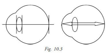
Optical axis
The optical axis of the eye is the distance from the corneal apex to the fovea. This is also the longest cornea-to-retina distance in the normal eye.
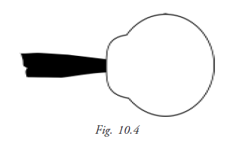
Corneal compression
The A-scan probe must come into contact with the cornea, either directly or through a liquid. If a corneal-contact method is used, there is a danger of the probe putting too much pressure on the cornea, causing the cornea to compress, which results in an artificial shortening of the axial eye length.
This is a potential source of significant error. A .4mm compression error can result in a 1 diopter error in the calculated IOL power.
Velocity of sound
Ultrasound travels at different speeds through materials of different densities. Ultrasound travel at high speeds through water and materials containing high water content.
The following are the speeds of ultrasound through the structures of the eye:
Cornea - 1640 m/s (meters per second)
Aqueous - 1532 m/s
Normal lens - 1640 m/s
Cataractous lens - 1629 m/s
Vitreous - 1532 m/s
Spike height
In A-scan biometry, one thin and parallel sound beam is emitted from the probe tip at a given frequency of approximately 10 MHz. An echo bounces back into the probe tip as the sound beam strikes each interface. An interface is the junction between any two media of different densities and velocities, which, in the eye, include the anterior corneal surface, the aqueous/anterior lens surface, the posterior lens capsule/anterior vitreous, the posterior vitreous/retinal surface, and the choroid/anterior scleral surface.
IOL Power with biometry
Biometry essentially consists of a keratometric reading (K) together with an ultra sonic measurement of axial length (AL) of the eye, perhaps with anterior chamber depth (ACD). Biometric information is fed into the variety of formula to calculate the IOL power. Formulae can be broadly divided into two groups.
- Theoretical formulae
- Regression formulae
Theoretical formula
Various theoretical formulae derived from the geometric optics as applied to the schematic eyes using theoretical constants have been developed to calculate the power of IOL required for post operative emmetropia. These formulae are based on 3 variables
- The axial length of eye ball (AL)
- Keratometric reading (K)
- The estimated post operative AC depth (ACD)
Binkhorst formula
P = 1336(4r-d) / (a-d) (4r – d)
P = IOL power in diopters
r = corneal radius in mm
a = axial length in mm
d = assumed post operative anterior chamber depth + corneal thickness
Regression formula
These formulae are based on regression analysis of the post operative results of implant power using variables of corneal power and axial length. A number of regression formulas are available. The commonly used are the SRK formula and its modification.
SRK I formula
P = A – (2.5 L – 0.9 K)
P = IOL power
A = Constant specific for each lens
L = Axial length
K = Average keratometry in diopters
It was introduced by Sanders, Retzlaff and Kraft based on the regression analysis taking into account the retrospective computer analysis of a large number of post operative refractions.
SRK II formula
P = A –( 2.5 L – 0.9 K )
But A is modified on the basis of the axial length
If L is <20mm: A +3.0
If L is 20 – 20.99: A+2.0
If L is 21 – 21.99 = A + 1
If L is 22 – 24.5 = A
If L is > 24.5 = A – 0.50
SRK/ T formula
- It is a regression formula empirically optimized for post operative anterior chamber depth, retinal thickness, and corneal refractive index
- This combines the advantages of both the theoretical and empirical analysis. This formula seems to be significantly more accurate for extremely long eyes
Keratometry (or) Ophthalmometer
Keratometry is the measurement of a patient’s central corneal curvature. It provides an objective, quantitative measurement of corneal astigmatism, measuring the curvature. Keratometry is also helpful in determining the appropriate fitting of contact lens. The measurement of the curvature of the anterior corneal surface is done by using the first Purkinje image.
Kerotometry determines corneal curvature by measuring the size of a reflected “mire”. Doubling of image avoids problems from eye movements. Radius scale is determined and diopter scale is derived from the radius using the formula for surface power D= (n-l)/r,where n=1.3375, the “standardized” refractive index for the cornea. Keratometer measures only the central 3mm of the corneal diameter.
Principle of keratometry
It measures the size of image reflected from corneal surface, because cornea acts as convex mirror. When an object is in front of the cornea a virtual image is seen inside the convex mirror (cornea). The size of the image depends on,
1. The distance of the object and
2. The curvature of the cornea
For a fixed distance of the object the size of the image depends on the curvature of the cornea. Similarly for a given size of the image distance of the object is different depending on the curvature of the cornea.
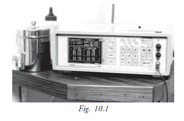
The object used is an illuminated circle with plus and minus images as shown in figure (fig 10.1 and 10.2). The two prisms inside the instrument give two additional images one displaced horizontally and another displaced vertically. Three images are seen as in figure while taking the reading the pluses and minuses coincide.
Keratometer set-up
- Focus the eye piece
- Set the adjustable eye piece so that it extends as for as possible - Place a white paper in front of the instrument objective to retro - illuminates the reticle
- Adjust the eye piece until the reticle is first seen in sharp focus - Ask the patient to remove his glasses
- Adjust height of chair and instrument to a comfortable position for both patients and examiner
- Unlock instrument controls (B& L. Keratometry)
- Instruct patient to palace his chin in the chin rest and forehead against the forehead rest
- Raise or lower the chin rest until the patient’s outer canthus is aligned with the hash mark on upright support or the pointer on the side of the instrument
Step- by-step procedure
- From outside the instrument, roughly align the telescope with the patient’s eye.
- Instruct the patient to look at the image of his eye in the keratometer.
- Look into the keratometer and align it by moving it from side to side or up and down until you can see the image of the mires (circle with plus and minus) on the patient’s cornea.
- Focus the mires and align them with the reticle in the lower right and head circle.
- Lock the instrument (B&L Keratometer only).
- Adjust horizontal and vertical power wheels until mires are in close apposition.
- Rotate the telescope to align spurs ( plus and minus signs) on the mires to 2 major meridians of the patient’s cornea.
- Adjust the horizontal power wheel until the vertical mires are co-incident.
- Adjust the vertical power wheel until the horizontal mires are co- incident.
- Readjust focus and / re-center reticle as needed.
- When mires are not clear lubricating drops can be used aand Keratometry can be performed again.
Recording
- Recording for each eye separately
- Record the power and meridian for horizontal meridian first (the primary meridan)
- Write a slash mark after the primary meridian and record the power and meridian for the vertical meridian (the secondary meridian)
- Record the amount of corneal astigmatism in diopters
- Record the type of astigmatism:
WR-With the rule
AR-Against the rule
OBL-Oblique
- Record the conditions of the mires e.g.MCAR- Mires Clear And Regular MIAD- Mires Irregular And Distorted
Example:
OD 42.50 at 180/ 43.50 at 90; 1.0D WR,MCAR
OS 47.37 at 180/ 41.37 at 90; 6.0D AR, Mires distorted
OD 41.75 at 180 / 43.75 at 70; 2.0D irregular astig; mires distorted
OS 43.12 at 135 / 41.87 at 45; 1.25D OBI; MCAR
OD 42.00/43.00 at 90; 1.0D WR MCAR
OS 42.00/42.00 at 90; sphere MCAR
(Meridian are expected to be 90 degree apart; therefore if only the meridian is recording the position of the other can be assumed to be 90 degrees away)
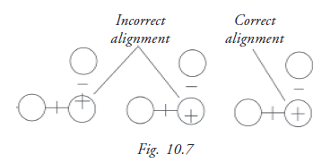
To obtain proper focus, rotate the focus knob until the bottom-right circles converge to form a fused image.(fig 10.7)
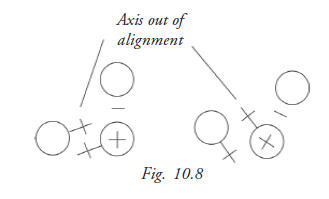
To locate the proper axis, rotate the keratometer until the pluses between the two bottom circles are in the same plane.(fig 10.8)
Student Exercise
I. Fill in the blanks
- Velocity of sound in cataractoues lens is __________
- SRK II formula is ___________
- Optical axis of the eye distance from __________ to ___________.
- An ultra sound beam will not through in __________
- Corneal compression caused by excessive pressure from the probe will cause _______ axial length.
II. Choose the best answer
- When performing Ascan biometry a one diopter IOL power error could result from an axial length of
a. 0.33mm
b. 0.03mm
c. 33cm
d. 3cm - The speed of ultra sound through vitreous is
a. 153.2m/s
b. 15.30m/s
c. 1532m/s
d. 15.30cm/c - A pseudophakia scan measure an eye that
a. Does not have a lens
b. Has an IOL place
c. Has a coneal transplained
d. Has a dense cataract
III True or false
- SRK/T formula is considered to bemost accurate for the eyes between 24.00mm to 28mm long.
- The image formed by the keretometer on the cornea are based on the principle of purkings Samson image.
- Regression formula of IOL calculation is based upon the patient’s old glasses prescription.
- Normal axial length 25.33mm.
IV Abbreviation
AR
WR
MCAR
MIAD
‘A’ scan A is ----