

Clinical Refraction Procedures
Retinoscopy
Retinoscopy is an objective method of measuring the optical power of the eye. A retinoscope is used to illuminate the inside of the eye, and to observe the light that is reflected from the retina. These reflected rays alter as they pass through the optical media of the eye, and by examining just how these emerging rays change, we determine the refractive power of the eye.
We describe retinoscopy as objective because we evaluate the eye as an optical instrument, initially ignoring any information the eye transmits to the brain. Thus retinoscopy does not depend on the patient’s vision or judgment.
Retinoscopy reduces refraction time and error by quickly determining the appropriate correcting lens, minimising the decisions the patient must make to refine the correction. Retinoscopy proves invaluable when patients cannot cooperate (infants, mentally retarded persons).
Evolution of Retinoscopy
- In 1859, Sir William Bowman commented on the peculiar linear fundus reflex he saw when viewing astigmatic eyes with H. Helmhohz’ new ophthalmoscope
- In 1873 Cuignet introduced the clinical use of retinoscopy in quantifying determination of refractive status
- In 1878 Landolt attempted to explain the optical concept underlying retinoscopy
- In 1880 Parent updated the optical theory of retinoscopy and initiated the name retinoscopy
- In 1920, Jack C. Copeland designed the streak retinoscope with rotating bulb to turn the streak to all ocular meridians. His original model was patented in 1927. He popularised the streak technique and revolutionized retinoscopy
Types of retinoscope
Reflecting (mirror) retinoscope: Mirror retinoscope is inexpensive and the most commonly used. A source of light is placed above and behind the patient. It may consist of single or plane mirror or a combination of plane and concave mirrors. There is a central aperture in the mirror (3-4mm in diameter) through which light enters the observer’s eye.
Self-illuminated retinoscope: These are costly but handy. These have become more popular recently. Two types of self-illuminated retinoscopes are available.
- Spot retinoscope: This projects light as a small circular beam on the retina
- Streak retinoscope: This projects light as a streak on the retina. This is popular as it makes determination of cylindrical power and axis easier
Design of self-illuminated retinoscope
It consists of two systems. Projection system and Observation system
Projection system
This consists of the following parts-
- Light source: A bulb with a linear filament that project a line or streak of light. Turning the sleeve on the instrument rotate the bulb, which in turn rotate the projected streak. This turning sleeve and rotating the light streak is called meridian control
- Condensing bulb: Resting in the light path, the lens focuses rays from the bulb on the mirror
- Mirror: Placed in the head of the instrument, the mirror bends the path of light at right angle to the axis of the handle. A beam projects from the head of the instrument
- Focusing Sleeve: This varies the distance between the bulb and lens to allow the retinoscope to project rays that either diverge (plane mirror effect) or converge (concave mirror effect). Hence, the sleeve is also called vergence control. In most instruments, the sleeve changes the focus (vergence) by moving the bulb up and down
- Current source: This is provided by a corded handle (connected to a transformer stepped down to 2.5v to 3.5v) or battery handle
Observation system
Peephole
Light reflected by the illuminated retina enters the retinoscope, passes through an aperture of the mirror and come out through the peephole at the rear end of the head. When we move the retinoscope we see movement of the streak /spot projected on the retina while looking through the peephole
Optics of retinoscopy
Before going into detail of the working principles of the retinoscope, understanding the far point concept of refractive error and its correction are necessary.
‘Far Point’ concept
Far point (FP) of an eye is defined as that point in space that is conjugate (corresponding to) with the fovea, when accommodation is relaxed. In retinoscopy retina is illuminated, locating the far point (FP) in space that is conjugate with it. If rays falling on retina come from infinity, it is known as emmetropia (normal vision)
- For emmetropia FP is at infinity
- For hypermetropia FP is beyond infinity
- For myopia FP lies somewhere in between infinity and the eye
While correcting refractive errors put the FP point at infinity.
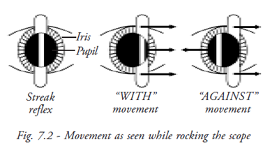
‘With movement’
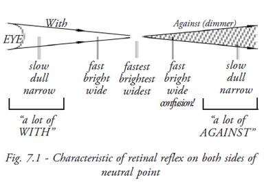
If the emerging rays have not converged to a point the retinal reflex will move in the same direction as the streak is moved (Fig. 7.1 and Fig. 7.2).
‘Against movement’
If rays have come to FP and diverge, the reflex will move opposite to movement.
Principle
In retinoscopy, 3 stages are present.
- Illumination stage: Light is directed into the patient’s eye to illuminate retina
- Reflex stage: An image of the illuminated retina is formed at the patient’s far point
- Projection stage: Moving the illumination across the fundus and noting the behavior of the luminous reflex locate the image at the far point
As the plane mirror effect is preferred universally, here image formation by plane mirror will be discussed.
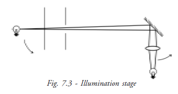
Illumination Stage
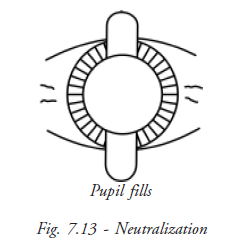
At this stage light is thrown from retinoscope to illuminate the retina (Fig. 7.3).
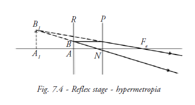
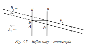
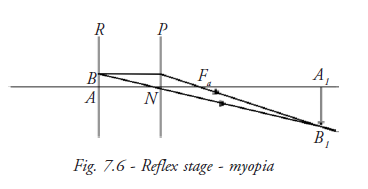
Reflex stage
An image A1B1 of the illuminated retina is formed at the patient’s far point. This image may be constructed using three rays (Fig. 7.4, Fig. 7.5 and Fig. 7.6).
- A ray from point A of the retina R on the principal axis of the eye, which leaves the eye along the principal axis
- A ray from retinal point B, off the principal axis, which travels parallel to the principal axis as far as the principal plane, P, of the eye, where it is refracted to pass onward through the anterior principal focus, Fa, of the eye
- A ray from retinal point B which passes undeviated through the nodal point
Projection stage
In hypermetropia and emmetropia the luminous reflex seen in the patient’s pupil moves in the same direction as the illuminating light- a “with movement” indicated by arrow in the figure (Fig 7.7, Fig. 7.8 and Fig 7.9).
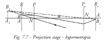
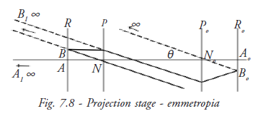
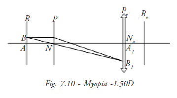
The point of reversal or neutral point of retinoscope is reached when the patient’s far point coincides with the observer nodal point.
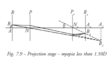
No image of B1 can be formed on the observer’s retina and at this point no movement of the reflex can be seen in patient’s pupil. The observer sees a diffuse bright red reflex. This is because the movement of the reflex is infinitely rapid.
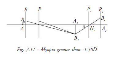
When the patient’s myopia exceeds the dioptric value of the working distance, the image A1B1 falls between the patient and observer.
The diagram shows that the luminous reflex now appears to move in the opposite direction to the illuminating light, “against movement”. Once again the luminous reflex appears to move more rapidly as the point of reversal is approached.
Prerequisite for retinoscopy
- A dark room
- Retinoscope
- A trial set
- A trial frame
- Distance fixation target preferably distance vision charts
Procedures in Performing the Retinoscopy
- The patient sits at a distance of 1meter/66 centimetre (as convenient to retinoscopist)
- Patient is asked to fix at a distant target to relax accommodation
- Then light is thrown on the patient’s eye from retinoscope
- By rocking the light slowly the characteristics of the reflex are observed
Characteristics of moving retinal reflex
Speed: In low degrees of refractive error the movement of the reflex is fast, whereas in high degrees of refractive error the movement is slow.
Brilliance:In low degrees of refractive error the reflex is bright whereas in high degrees of refractive error the reflex is dull.
Width: In low degree of refractive error the reflex is wide whereas in high degree of refractive error the reflex is narrow.
Working lens (neutralising lens)
Far point optics defines refractive error in terms of correcting lens that put the FP at infinity. But it is impossible to sit at infinity. Infinity can be simulated at any distance by placing a working lens before the eye. The power of this lens must equal examiners dioptric distance from the patient. The working lens makes the scope as if it were at infinity. For example, if the examiner sitting at 1meter distance has to put a working lens 1D in front of the eye, this 1D lens puts them at infinity and now neutralising can start.
Correcting lens
Use of the appropriate working lens places us at infinity. Correcting lens is the lens that
will bring FP to the examiner. Whatever correcting lens brings the FP to infinity is the
measure of refractive error (ignoring the power of working lens).
- Plus lenses pull FP towards the eye
- Minus lenses push FP away from the eye
Working distance
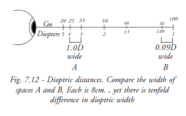
66 cm (26”) is a convenient working distance (roughly arm’s length) with suitably bright reflex. Dioptric value (1.5) is a round number to subtract. Error of 5cm in either direction causes error of only 0.12 D. If less working distance is used, (25cm) an error of a few centimeters can cause error up to 0.50D. Whereas more working distance (1 meter) reduce reflex. In dim light, it is difficult to change lenses from the trial frame (Fig. 7.12).
Neutralisation
In against movement, the far point is in between the examiner and the patient (Fig. 7.13).
Therefore to bring the far point to the examiner’s pupil, minus lenses should be placed, in
front of the patient’s eye. Similarly, in case of with movement, plus lenses should be
placed in front of the patient’s eye. When the neutralization point is reached there is no
movement of reflex. This leads to simple clinical rules:
- If with movement is seen add + lens (or subtract minus)
- If against the movement is seen add minus lenses (or subtract plus lenses)
Lens power should be added or subtracted until neutrality is reached.
Finding spherical power
Sphere
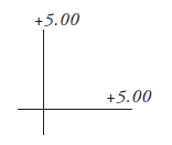
When both principle meridians require the same correcting power.
Finding cylindrical power
With two spheres
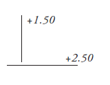
Neutralise one axis with one spherical lens. If the 90-degree axis is neutralised with a +1.50D sph and the 180-degree axis is neutralised with 2.50D sph., the gross retinoscopy will be +1.50Dsph /+1.0cyl 90degree. The examiners working distance should be subtracted from the sphere to obtain the refractive correction.
With a sphere and cylinder
First neutralise one axis with an appropriate spherical lens. (In order to keep working using ‘with reflexes’, neutralise the less plus axis first). With this spherical lens in place, neutralise the other axis 90 degrees away with a cylindrical lens at the appropriate orientation. The spherical - cylindrical gross retinoscopy may be read directly from the trial lens apparatus.
With two cylinder
Although it is possible to use two cylinders at right angles to each other for the gross retinoscopy, there is no advantage of this variant over the spherocylinder combination.
Finding cylinder axis
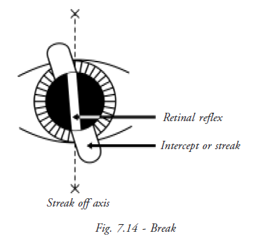
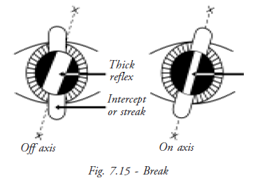
Break
Break is observing the alignment between the reflexes in the pupil and the band outside it. When the streak is not parallel to one of the meridians, the band of light in the pupillary area lies in a position intermediate between the bands outside the pupil and that from the axis cylinder. The axis even in the case of low astigmatic errors can be determined by rotating the streak until the break disappears. The correcting cylinder should be placed at this axis (Fig. 7.14).
Width
The width of the streak varies as it is rotated around the correct axis. It appears narrowest when the streak aligns with the true axis.
Intensity of reflex
The intensity of the line is brighter when the streak is on the correct axis.
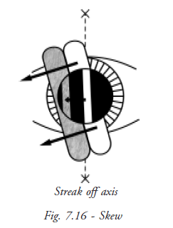
Skew
Oblique motion of the streak reflex may be used to refine the axis in small cylinders. If the streak is off axis, it will move in a slightly different direction from the pupillary reflex (Fig. 7.16). The reflex and streak move in the same direction (both at the right angle to the orientation of the streak) when the streak is aligned with one of the principle meridians.
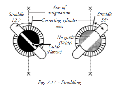
Straddling
This technique is performed with the estimated correcting cylinder in place (Fig. 7.17). The retinoscope streak is turned 45 degrees from the axis in both directions, and if the axis is correct the width of the reflex will be equal in both off axis positions. If the axis is incorrect, the width will be unequal in the two positions. The axis of the correcting cylinder should be moved towards the narrower reflex and straddling performed again.
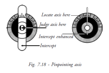
Pin-pointing axis
We can pin-point exact axis by reducing the sleeve width and checking the axis with trial frames.
Tips
- It is easier to work with the brighter, sharper with image; it is preferable to over minus the eye, and obtain with reflex and then reduces the minus (add plus) until neutrality is reached
- Be aware that the full dull reflex of high refractive error may be confused with the pupil neutrality reflex or with dull reflexes seen in patients with hazy media, high plus or minus, and check again
- Confirm the neutralization point by adding +/- 0.25D to observe the change of movement
Summary
Retinoscopy is an objective method of measuring the optical power of the eye. Jack C. Copeland popularised streak retinoscopy. Though mirror and spot retinoscopes are still in use, the streak retinoscope is most popular. Streak retinoscope aids in finding the correct cylindrical power and axis. Optics behind retinoscopy are simple. The retina is illuminated to locate the far point and neutralise it by using correcting lens. If working lens are used it is not necessary to subtract working distance from the power obtained from neutralisation. 66 centimeters is the standard working distance used universally as distance error is minimal. Using different techniques like skew, straddling and pin-pointing correct cylindrical axis is found.
Student exercise
Answer the following
- Why is retinoscopy known as objective retinoscopy? What is its significance?
- Describe the design of the streak retinoscope.
- What is the far point? What are the stages involved in retinoscopy?
- Why is 66 centimeters working distance used?
- What are the special techniques used in finding axis of cylinder?
Subjective Refraction
Subjective refraction comes after objective refraction. Patients are asked to approve or refine the objective findings. In subjective examination, the patients are asked what lenses help them to see well. It includes optical science; it also involves physiological conditions of the eye and socio-economical background and psychological state of the patient.
Definition
Subjective refraction is the term applied to the technique of comparing one lens against another according to the patient preference, using changes in the vision as criterion to arrive at the dioptric lens combination that results in maximum visual acuity. (Polasky, 1991)
Factors influencing the response of the patient
- Refractive status of the eye
- Pathological condition of the eye
- Neurological condition of the eye
- Socio-economic background of the patient
- Intelligence of the patient
- Emotional state of the patient
Gaining patient confidence
Being a good retinoscopist does not always make a good refractionist. It’s the patience and the expertise of dealing with patience that are required skill. Put the patient at ease by gaining their confidence. They will cooperate wholeheartedly.
- Ask patients simple questions and frame easy choices for them
- Explain to the patient what the retinoscopist prefer is the outcome. Since there is no right or wrong answer, there cannot be mistakes
- Give time for the patient to think and decide
- Be friendly with the patient
Pre-requisite for subjective testing
- Dark room
- Illumination
- Proper sitting arrangement
- Visual acuity chart (distance and near)
- Trial set
- Trial frame
- Jackson’s cross cylinder
- Astigmatic dial
Trial-set accessories
- Occluder
- Pinhole
- Stenopaic slit
- Maddox rod
- Red and green glass
- Prism
Pinhole
Pinhole accessory consist of an opaque disc with a pinhole (PH) of 1 to 2mm in diameter in its center.
Optical function of pinhole
The pinhole allows the passage of only central rays of light. This permits the formation of a clear retinal image.
Size of pinhole
Size of PH may vary
Smaller PH: (diameter less than 1mm) introduces diffraction and further restricts retinal illumination, resulting in dim, unfocused retinal image.
Large PH: (diameter greater then 2mm) approximate human pupil and is ineffective.
Ideal PH: 1.32mm diameter is most effective (Lebensohn, 1950) because it produces the smallest blur circle size.
Multiple pinholes: Michaels (1985) suggested use of multiple pinholes in order to boost retinal illumination and ease the patient use.
Use of pinhole - assuring optical quality of the eye
Use of the pinhole allows the eye’s potential visual acuity to be expressed. Vision with PH is compared to vision without pinhole.
- If patient’s vision improves with pinhole, the patient has an uncorrected refractive error
- If patient’s vision does not improve then patient may have a pathological defect or
neurological defect
Point to be noted: When size of the pupil is small use of the PH will be of little diagnostic value (Hyperopia, aging, miotics)
Stenopic slit
The Stenopic slit consists of a rectangular aperture ranging from 0.5mm to 1.0mm in width and up to 15mm in length.
Optical function of stenopic slit
The width of the stenopic slit approximates that of pinhole and is assumed to limit admission of light rays to approximately one meridian. Thus the stenopaic slit acts like a pinhole to reduce the size of blur circle in the meridian at right angle to the slit, yet allows blur circle size to be unchanged in the meridian coincident with it.
Use
- To find astigmatic power and axis
- To measure vertex distance
Finding astigmatic power and axis
Stenopic slit is placed in front of the eye and rotated until position of better visual acuity is found. Then the position is fogged and unfogged to get best visual acuity. This position represents axis of the cylinder. When the slit is rotated to the other principle meridian, visual acuity is poorer in this position. This position is fogged and unfogged until the best visual acuity is reached again. The difference between powers found for the two primary meridians is the cylindrical component of refractive error with its axis perpendicular to the second slit position.
Measurement of vertex distance
Vertex distance can be measured using Stenopic slit. A thin ruler is entered through the slit to touch the eyelid of closed eye. The distance between the Stenopic slit and eyelid is the vertex distance. 1mm is to be added for thickness of closed eyelid.
Red and green lens
Red and green lenses are primarily used before an eye to interrupt fusion in the assessment of binocularity. These are used for Worth four dot test, FRIEND test and stereopsis.
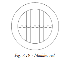
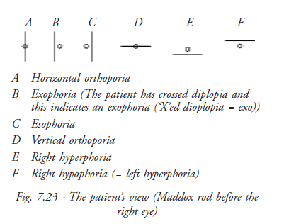
Maddox rod
Maddox rod consists of a series of powerful convex cylindrical lenses, mounted side by side in a trial lens. The glass of Maddox rod is tinted red (Fig. 7.19).
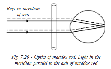
Optical function of maddox rod
Maddox rod is placed in front of one eye. Patient sees a white spotlight kept at infinity. When light passes parallel to axis of cylinder, it goes undeviated and brought to focus by eye (Fig. 7.20).
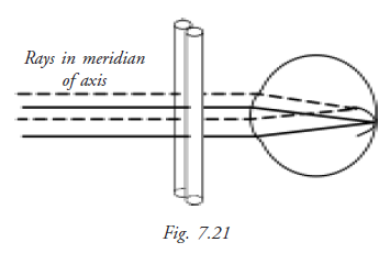
The Maddox rod consists of a series of plus cylinders, forming a row of foci on the retina. These foci join up and are seen as a line of light, which lies at 900 to the axis of the Maddox rod.
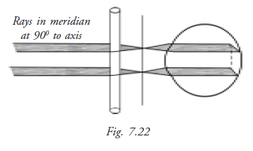
Light incident on the Maddox rod in the meridian perpendicular to its axis is converged by each cylinder to a real line focus on the retina.
Use
Maddox rod is used in the diagnosis of phoria and tropia.
- Maddox rod is conventionally placed in front of the right eye.
- A distant white spot light source is viewed through both eyes.
- Right eye sees the red line at 900 to the axis of Maddox rod, left eye sees the spotlight.
• Two eyes see dissimilar images, dissociated, allowing any muscular imbalance to become manifest.
Steps of subjective refraction
- Starting point
- Control of accommodation
- Astigmatic correction
- Monocular spherical end point
- Binocular balance
Starting point
The corrections of refractive error determined by the objective technique are placed into the lens aperture of trial frame. The objective results acts as a starting point from which the subjective refraction can take place. Alternatively, the habitual spectacle correction or result of previous subjective refraction may suffice as the starting point. The geometrical center of the trial lens of 1cm apertures are aligned with the patient’s visual axis and the appropriate vertex distance and pantoscopic angles are achieved.
Control of accommodation
Controlling accommodation (i.e. relaxing accommodation) is essential because fluctuating accommodation may confuse retinal focus presented by each change of lens combination. Accommodation may be controlled by three classic means: - Cycloplegic refraction, Non Cycloplegic refraction and Fogging
Cycloplegic Refraction
Cycloplegic refraction means refraction under cycloplegia of ciliary muscle. Cycloplegic eye drops (atropine, cyclopentolate and tropicamide) are instilled to achieve cycloplegia (paralysis) of ciliary muscles, which results in full relaxation of accommodation.
It is recommended when patients have the following situations:
- Asthenopic symptom
- Hypermetropia
- Convergent strabismus
- Active accommodation
As accommodation is fully relaxed, patients accept more plus correction. This correction results in blurred vision after the effect of cycloplegia diminishes. Drug correction is done on total correction accepted by the patient. Sometimes a second refraction is required after the effects of cycloplegia have cleared.
Drug Correction
It is an arbitrary modification of the result of cycloplegic refraction for giving spectacle prescription. We subtract a value depending on the nature of Cycloplegic used.
Non-Cycloplegic refraction
In this case the patient is asked to fix at a distant large target. This relaxes accommodation adequately.
Fogging technique
In this technique the initial objective is to blur the vision by adding plus(+) spherical lens or reduction of minus(-) spherical lens to reduce visual acuity to Snellen’s 6/36 .Then plus power is reduced before the eye or minus power is added in steps of 0.25D until visual acuity improves to the point that the patient can distinguish small letters of chart presented at distance. This process is called unfogging.
Astigmatic correction
The major effort in subjective refraction is to determine the astigmatic component of refractive error. Hence a large number of techniques have been developed for the accurate measurement of astigmatism. There are two main techniques usually followed.
Testing astigmatism under fog
In this technique a spherical correcting trial lens combination is placed in front of each eye. This places foci of both principal meridians in front of the retina. Then astigmatic dial is used to find the axis of cylindrical component of error (Fig. 7.24).
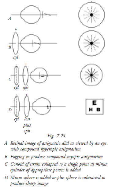
Technique
- Obtain best-corrected visual acuity using sphere
- Fog the eye to about 6/60 by adding plus sphere
- Ask patient to note blackest and sharpest line of astigmatic dial
- Add minus cylinder with the axis perpendicular to the blackest and sharpest line until all lines appear equal
- Reduce plus sphere (or add minus sphere) until best acuity is obtained with visual acuity chart.
- All lines of the dial now appear equally black and sharp
Testing astigmatism without fog
The major technique in use today for determination of axis and power of cylindrical component of refractive error is JCC (Jackson Cross Cylinder), also known as flip cross technique. This technique does not require the eye to be fogged for proper performance. In fact the technique is best performed when the circle of least confusion is on the retina.
Jackson cross cylinder
JCC was first described by Jackson in 1887 for determination of power and 1907 for axis of cylinder.
Construction of JCC
It is a spherocylinderical lens in which the power of the cylinder is twice the power of sphere and of opposite sign. E.g. +0.50DSph is combined with –1.0DCyl. This results in a net power meridional refractive power of +0.50DC in one meridian and –0.50Dc in the other meridian.
The principle meridians are marked at the periphery of the lens to be visible by the examiner. The handle is attached midway between two marked meridians.
Technique
Axis check
- Position the cross cylinder axis 450 from the principal meridian of the correcting cylinder
- Determine preferred flip choice
- Rotate the axis towards the corresponding axis of cross cylinder (plus cylinder axis rotated to + cylinder axis of JCC, minus cylinder axis rotated to - cylinder axis of JCC)
- Repeat until two flip choices are equal.
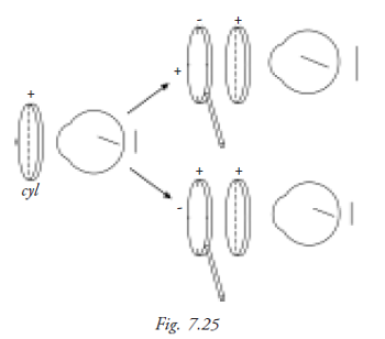
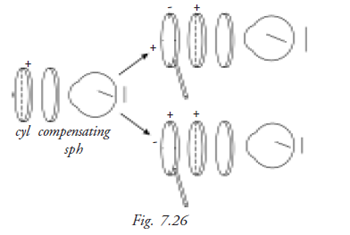
Power check
- Align JCC axes with the principal meridians of correcting cylinder (Fig. 7.25 and Fig. 7.26)
- Determine preferred flip choice
- Add or subtract cylindrical power according to the preferred position of cross cylinder
- Compensate for change in position of the circle of least confusion by adding half as much sphere in the opposite direction.
Monocular spherical end point
Duochrome test
This test is used to find the monocular endpoint of refraction (Fig. 7.27). Each eye is tested separately to find out if the eye is over corrected or under corrected. This test was introduced by Brown (1927), but it lapsed into disuse until reintroduced by Freeman (1955).
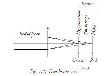
Principle
Chromatic aberration, the basis of the test, occurs because different wavelengths of light are bent to a different extent. The longer wavelength (red) is refracted less than the shorter (green). If the letters on the red side stand out more, add minus power; if the letters on the green side stand out more, add plus power. Neutrality is reached when the letters on both backgrounds appear equally distinct.
Technique
- One eye is occluded
- Subject is asked to note whether the letters on the chart are equally visible or prominent on both backgrounds or more visible or prominent against one of the backgrounds
- Vision is slightly fogged by adding plus(+) sphere monocularly in 0.25DS steps until red background letters become more prominent
- This should occur in only one / two increments of plus power unless the eye has been over corrected
- The plus powered sphere before the eye is reduced until both background letters appear equally distinct. This represents optimum correction
- Next reduction causes green to be more prominent
Binocular balancing
Binocular balancing is not only balancing the visual acuity, but also balancing accommodation
Technique
Place the final distance correction in the trial frame with the patient viewing 6/18 line target with both the eyes.
Add +0.75 D sphere to both eyes and ask the patient whether the vision became blurred. This step is fogging.
Tell the patient to keep both eyes open. One eye is covered then the other eye and the patient is asked which eye sees better.
Add +0.25 D sphere to the better seeing eye and repeat the above step. Continue until both eyes are equally blurred. Slowly defog until the patient can read the 6/6 line.
Points to be noted after duochrome test
If a change in lens power produces immediate reversal of choice from red to green, spherical power that gives better perception of green is the appropriate end point. This especially occurs in young patient with active accommodation.
- Older patients are red biased because of the changes in crystalline lens.
- This test is equally relevant for patients with color deficiency as chromatic aberration is still present in their eyes. Instruct the patient to evaluate the prominence of letters, not colors.
- Instruct patient to notice clarity, darkness, definition of black letters not their background as intensity of chart colors may vary among different manufactures.
Students Exercise
Answer the following
- Explain the difference between subjective and objective refraction.
- List three factors that influence patient response in subjective refraction.
- Why is the control of accommodation important?
- What ocular medication is used in refraction?
- Explain how to refine the cylindrical axis.
- Describe the duochrome test.
- Explain with diagram the optical function of Maddox rod.